Reverse Engineering
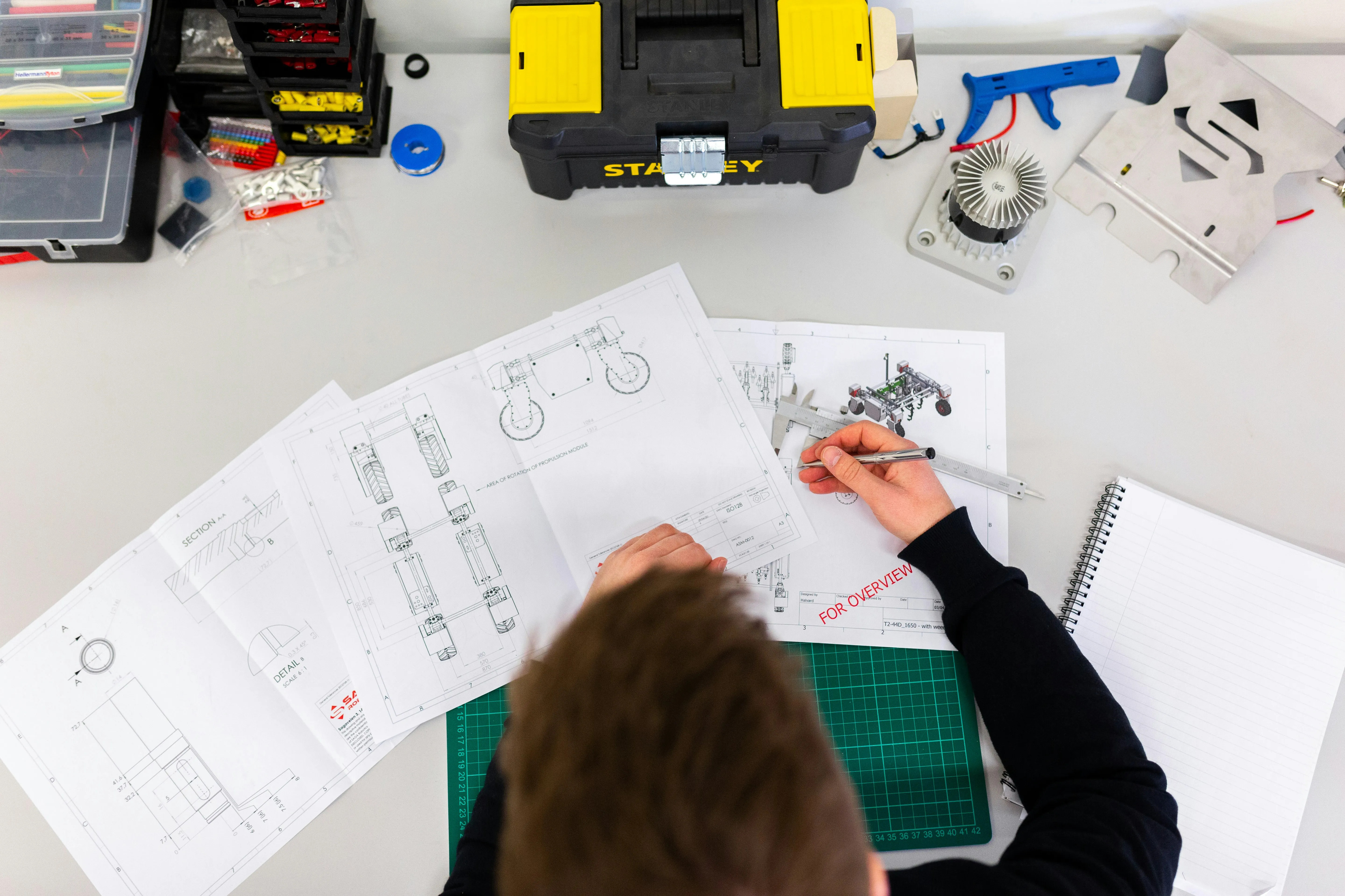
Reverse engineering of Printed Circuit Board Assemblies (PCBAs) involves the process of analyzing an existing circuit board to understand its design, functionality, and components without access to the original design documentation. The process is often done due to Legacy systems, competitive analysis, cost reduction, security analysis.
.webp)
At Indic EMS Electronics, we understand that innovation often requires looking back to move forward. Our Reverse Engineering services in electronic manufacturing empower you to decode, understand, and enhance existing electronic products.

Our reverse engineering services are tailored to your specific needs. Whether you're looking to upgrade, modify, or troubleshoot, Indic EMS Electronics provides bespoke solutions that align seamlessly with your objectives. From initial analysis to digital modeling and implementation, we offer comprehensive support throughout the reverse engineering process, ensuring a smooth and efficient transition from concept to reality.
.webp)
Our Capabilities
1. Define: During the Define Phase, the product’s functional / performance requirements are defined along with the VOC. The Marketing and Product Management divisions of an organization are usually the primary sources of this information. The design specifications are integrated into one or more concepts to be reviewed by the project team. The management team should develop a Project Charter. The information contained in the charter should include, but is not limited to, the following:
- Background Information
- Primary Objectives
- Project Scope
- Key Deliverables and Dates
- Project Budget
- Identify Stakeholders and Sponsor
- Identify Project Manager and Define the Team
- Review Possible Constraints / Assumptions / Concerns /Risks
2. Feasibility: The purpose of the Feasibility Phase is to allow management an opportunity to evaluate the project’s potential for success. During the Feasibility Phase, the project team reviews the product design concepts and selects the design that best fulfills the previously defined requirements. The business case is reviewed and refined. The outputs or deliverables of the Feasibility Phase should include (but are not limited to):
- Boundary Diagram: A graphic tool defining the scope of the project, along with internal and external interactions
- Preliminary Design Concept: Includes a high level Bill of Material (BOM)
- Process Flow Diagram: Outline the basic processes required for production
- Develop: The Develop Phase activities are focused on advancing the product design features and characteristics into amore defined form while assessing risk in the design. A validation plan is also developed during this phase. A comprehensive review of the design is performed to evaluate the robustness of the design and its ability to meet customer and performance requirements. DFM/A activities are initiated prior to design completion or design freeze.
- Validate: During the Validate Phase, product analysis and testing are performed. Some testing cannot occur until prototype parts are available. Design changes are possible due to the results of validation testing but very costly. In addition, the manufacturing process is developing and process risk is being analyzed and addressed. The major steps of the manufacturing process are being developed and reviewed. Product analysis and the testing schedule are being developed and prototype parts completed. Some of the common outputs of the Validate Phase are listed below:
- Packaging Standards
- Production Level Drawings
- Design Validation Plan and Report (DVP&R)
- Process Flow / Process Mapping
- Process Failure Modes and Effects Analysis (PFMEA)
- Review Supplier Production Part Approval Process (PPAP) Submissions
- Prototype – Process Work Instructions
- Fixture / Tooling Creation and Build
- Prototype Build
5. Implement: During the Implement Phase of the NPI process the manufacturing processes are refined and validated through pilot builds and capability studies. In addition, process documentation and quality controls are being developed and implemented. Furthermore, various other activities are on-going including, but not limited to, the following examples:
- Development of Manuals
- Pricelist / Catalogue / Quote Tool
- Process Work Instructions and Standard Work
- Approval of Supplier PPAP Submissions Internal Training of Associates
- External Training of Sales, Dealers, etc.
- Production Control Plans
- Significant Production Run / Pilot Build
- Process Capability Studies / Statistical Process Control (SPC)
- Packaging Evaluations
- Final Safety / Regulatory Review
6. Evaluate: The Evaluate Phase serves several purposes in the product introduction process. This phase provides the team an opportunity to tie up any remaining documentation tasks, review process performance and collect customer feedback on the new product. The team should also take this opportunity to review any lessons learned and document them for use in future projects. One tool that has proven effective for some organizations is the TGR/TGW exercise. TGR/TGW stands for “Things Gone Right / Things Gone Wrong”. During this exercise the team gathers to take an objective look at the project. Discussion revolves around all the things that went well and the things that may not have gone well or could have been improved. The causes of the TGWs are examined and counter measures developed to prevent re-occurrence in the next project. The TGRs should be carried over to future projects as a continuous improvement effort within the NPI process. The integration of lessons learned into future projects essentially closes the loop in NPI, helping to retain valuable information and develop a more robust and progressive NPI process.


